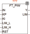
| Input IN |
REAL (input signal) |
| KP |
REAL (proportional part of the controller) |
| KI |
REAL (integral part of the controller) |
| LIM_L |
REAL (lower limit of the integrator output) |
| ILIM_H |
REAL (upper limit of the integrator output) |
| RST |
BOOL (asynchronous reset input) |
| Output Y |
REAL (output of the controller) |
| LIM |
BOOL (TRUE if the output has reached a limit) |
| FT_PIDW is a PID controller with Anti Wind- Up Hold works according to the following formula |
|
|
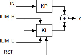
Y = KP * IN + KI * INTEG(IN) |
| The input values LIM_H and LIM_L limit the range of the output Y. With RST, the internal Integrator can always be set to 0. The output LIM indicates that the Output Y runs to one of the limits LIM_L orL IM_H. The PI controller is free running and uses the trapezoidal rule to calculate the integrator for the highest accuracy and optimal speed. The default values of the input parameters are predefined as follows |
KP = 1, CI = 1, ILIM_L= -1E38 and ILIM_H = +1E38. |
| Anti Wind-Up |
Control modules with Integrator tend to the so-called Wind-Up Effect. A Wind-Up means that the integrator module continuously run again because, for example, the control signal Y is at a limit and the system can not compensate the deviation, which then leads to subsequent transition into the control range until a long and time-consuming dismantling of the integrator value and the scheme only respond delayed. Since the integrator is only necessary to compensate the deviation for all other control units, and the range of the integrator should be limited with the values of ILIM. |
|
The module FT_PIDW has a so-called Wind-Up-Hold which freezes the integrator after reaching for an output limit (LIM_L, LIM_H) on the last value and thus a Wind-Up prevents. |
| The following graph illustrates the internal structure of the controller |
|
|
FT_PIW can used together with the modules CTRL_IN and CTRL_OUT to build complex controllers. |